Description
Scaring devices for seed –
and crop protection
TRIPLE – JOHN CAROUSEL
INSTRUCTION MANUAL
PURIVOX TRIPLE-JOHN ELECTRON INSTRUCTION MANUAL
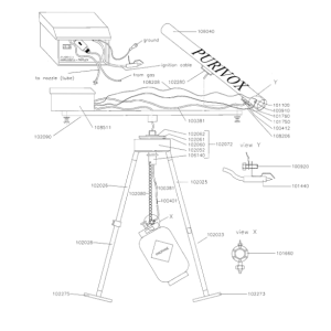
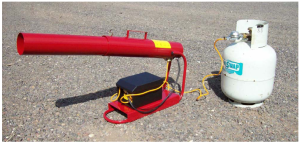
When unpacking the PURIVOX TRIPLE-JOHN ELECTRON bird scaring cannon , you will find the following components:
Main Power Controller ( Black plastic electrical case with attached cables and hoses See Figure 1 )
- One megaphone with fastening screw
- One cross-bar ( rotating beam )
- One bag containing the chain
- One bag containing the tripod centre piece
- Propane pressure reducer with hose ( to be screwed into the propane tank )
- Three tripod legs ( each leg consisting of two tubes which slide together)
It is advisable to identify all parts before proceeding with assembly of the cannon.
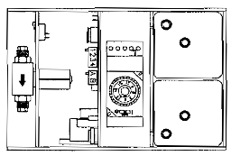
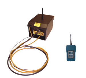
The POWER CONTROL BOX
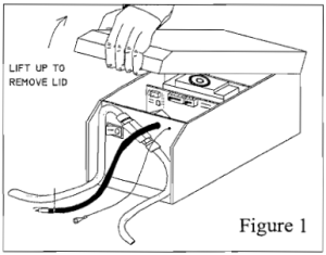
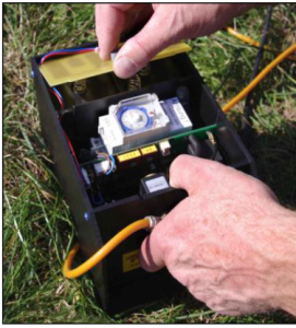
The main power controller is housed inside a black weather-resistant plastics case. To access the control circuitry remove the protecting lid by lifting the front of the lid as shown in Figure 1 .
Inside you will find the:
- Battery plate & compartment
- Electronic ( on / off) timer
- Shot frequency switch
- Shot sequence switch ( 1-4 shot’s)
- Sound level switch
On the outside of the control box you will see the ON/OFF switch, spark plug & ground wires, as well as the propane gas valve with attached hoses.
All items are shown on Figure 2.

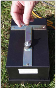
INSTALLING BATTERIES
Before installing the batteries, ensure that the On/Off switch located on the outside of the POWER CONTROLLER case is in the ” O” ( Off) position.
To install the batteries, gently pull-up on the “battery plate lock” while lightly pressing the battery plate lock towards the timer. ( See Figure 3.1 ) Insert two 6-volt lantern style batteries into the battery compartment. The orientation of the batteries is not important, just ensure that the spring terminals of each battery are facing up ( Figure 3.2) Now insert the battery plate into the slot located on the back wall of the battery compartment ( Figure 3.3) and press
the opposite side of the battery plate down until into position ( Figure 3.4)
FIGURE 3
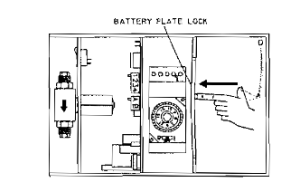
3.1 — to open the battery compartment, press the centre wall between the battery compartment and the timer. the battery plate will then release.
3.2 – Insert two 6-volt batteries into battery compartment ensuring that the spring contacts are facing upwards.

3.3 – Insert battery plate into the slot located on the back inside wall of the battery compartment

3.4 – Press down on the opposite edge of the batte1y plate until the plate snaps into place.
IMPORTANT: The batteries MUST be removed when the cannon is stored for the winter. One set of batteries should last for the entire “bird season”.
SETTING THE SHOT FREQUENCY
The SHOT FREQUENCY slide switch located on the circuit board INSIDE the POWER CONTROLLER CASE sets the time interval between each shot sequence. In order to make the TRIPLE-JOHN Carousel’s firing sequences as unpredictable as possible, the timing intervals are randomized by the computer circuitry. The user, however, can select maximum and minimum time values between which the computer chooses random firing intervals. These settings are as follows:

| Switch Position | Timing Cycles |
| 1 | shots occur between 2 – 4 minutes |
| 2 | shots occur between 4 – 8 minutes |
| 3 | shots occur between 8 – 16 minutes |
| 4 | shots occur between 16 – 32 minutes |
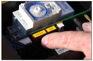
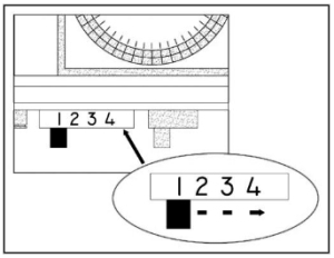
SETTING THE SHOT SEQUENCE
SHOT SEQUENCE SWITCH

Changes only during DEVICE is Switched OFF ! Wait minimum 15 seconds before Switch on.
1 Shot = both Switches up
2 Shots = left up, right down
3 Shots = left down, right up
4 Shots = both Switches down
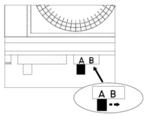
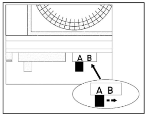
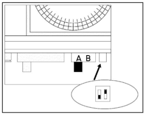
SETTING THE SOUND LEVEL
 The PURIVOX TRIPLE JOHN ELECTRON can be operated at two sound-intensity levels. In order to operate LEVEL SWITCH ( located on the circuit board inside the operate the cannon at a reduced sound level, the SOUND : position.
” A” = REDUCED sound output
” B” = FULL sound output
SETTING THE TIMER
The programmable ON/OFF timer is located inside the POWER CONTROLLER CASE.( See Figure 6 ). Once the batteries have been installed, the quartz timer will start to “tick”. To set the timer, lift the clear plastic cover which protects the time scale.
The timer is calibrated based on the 24-hour clock – i.e.:
6:00 a.m. = 6
9:00 a.m. = 9
12:00 noon= 12
3:00 p.m. = 15
6:00p.m. = 18
9:00p.m. = 21
12 midnight = 0
IMPORTANT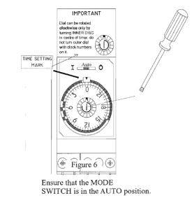
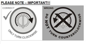
Only use the small screwdriver ( enclosed in the power controller ) to rotate the time dial. The DIAL can only be rotated by turning the WHITE DISC located in the centre of the time dial. See Figure 6. Do not attempt to tum the outer dial itself.
ONLY TURN DIAL IN THE DIRECTION OF ARROW
Turning the time dial backwards will void the warranty .
The time-setting keys are positioned around the entire dial. Each key represents a 30-minute time interval. These keys are used to set the daily START-UP and SHUT-DOWN times of the cannon.
During the period when the time-setting keys are pushed outward ( away from the centre of the dial), the cannons is ON. When the time-setting keys are pushed inward ( towards the centre of the dial), the cannons is OFF.
Time-setting keys OUTWARD = Cannon ON
Time-setting keys INWARD = Cannon OFF
Once the desired timing program has been set, the timer must be set to the present time of day.
Using the screwdriver, turn the dial ( using the white disc located in the centre of the time dial) in a clockwise direction until the present time of day lines up with the TIME-.SETTING MARK (See Fig. 6 ).
TIMER Set – up EXAMPLE
YOU want the cannon to:
- Come on at 6:00 a.m.
- Run all day
- Shut off at 9:00 p.m.
- The “Present time of day” is 3:00 p.m.
Steps:
- Lift the timer cover cap
- Slide the time-setting key next to the “6” outward ( away from centre of dial)
- Carefully slide the time-setting keys between 6 and 20 Stop when you have reached the number “21” ( Remember that “21” means 9:00 p.m.).
- Slide the time-setting key next to the number 21 inward ( towards the centre of the dial)
- Now continue sliding the time-setting keys inward until you reach the number “6”.( All keys between the numbers “6” and “21” should be positioned OUTWARD ( CANNON IS ON) while the keys between “21” and “6” should be positioned INWARD ( CANNON IS OFF).
- Set the time by aligning the present time of day with the TIME-SETTING For our example, align the “15” ( 3:00 p.m. ) with the time-setting mark.
- Ensure that the time mode selector switch is in the AUTO position.
- Close the timer.
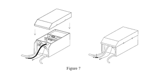
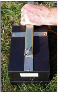
Once the timer has been set and the shot timing cycles have been selected, and the sound power level has been set, replace the controller cover as shown in Figure 7.
ASSEMBLING THE CANNON
- TURN THE ON/OFF SWITCH ON THE OUTSIDE OF THE MAIN POWER CONTROL UNIT TO THE “O” (OFF)
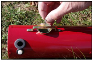
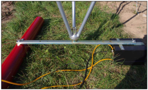
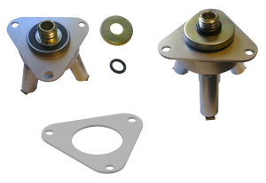
- Securley fasten the main power controller to the cross bar using the wingscrew, washer and lockwasher – use the outer-most hole on the crossbar such that the controller is positioned at the crossbar ( with the cables and hoses facing inward ).
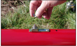
- Attach the megaphone to the crossbar Be sure that the hole for the spark plug faces inward ( towards the power controller)
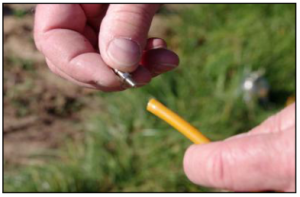
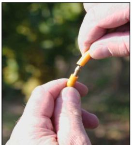
- Screw the spark plug ( # 101440) and the ground cable ( # 108208) into the megaphone in the following manner:
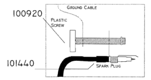
- (a)pick up plastic screw # 100920
(b)slide ground cable lug over screw
(c)slide spark plug lug over screw
(d)screw into
IMPORTANT: If the order of the components is not correct, the cannon will not operate properly.
- (a)pick up plastic screw # 100920
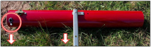
- Remove the propane jet ( # 100412 ) from the jet hose ( # 100381 ). Screw the propane jet into the megaphone ( back, underside) and slide the jet hose over the installed
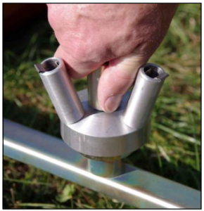
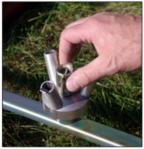
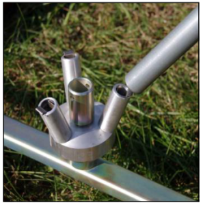
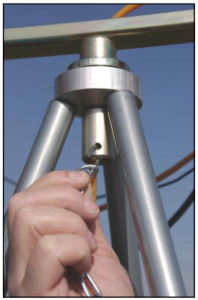
- Screw the tripod centre piece ( # 102072) into the centre of the crossbar ( # 102090 ).
- Feed the other jet hose down through the tripod centre piece ( See Assembly Diagram).
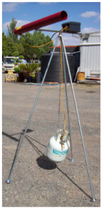
- Assemble the tripod legs by inserting the upper sections ( straight tubes) into the lower sections ( tubes with attached stabilizing plates ). Push the assembled tripod legs over the stubs on the tripod centre piece (# 102072 ). The spring clips on the tripod centre piece will hold the legs in The cannon should be leveled using the adjustable leg and should spin freely.
- Thoroughly clean the valve cup on the propane Seat the propane regulator by repatedly twisting the cone into the cup on the propane bottle. Then tighten the nut (left-hand thread ! ). If the regulator is not properly seated, or the cup is not clean, the connection may leak.
- Using the attached hose Connect the jet hose from the regulator to the jet hose coming down through the tripod centre piece.
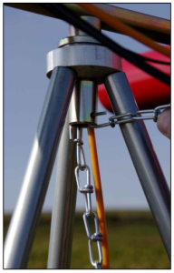
- Connect one end of the chain ( # 102080 ) into the hole on the bearing tube ( # 106140 ). The other end should be fed throug the handle on the propane tank and linked back into bearing
STARTING THE CANNON
The cannon should always be started in a controlled manner so that the operator, is not subjected to the cannon shot at close range. Always start the cannon by following these steps:
- Tum the ON/OFF switch ( located on the outside of the POWER CONTROLLER BOX ) to the “0” (OFF)
- Open the valve on the propane gas tank.
- Tum the ON/OFF switch to the “1” (ON) position.
The first series of shot will occur after approximately 10 seconds. Protect your ears and move away from the unit.
Warning: If these steps are not followed the cannon may fire IMMEDIATELY after the propane tank valve has been turned on or the power switch has been turned on
STORING THE TRIPLE JOHN
- Remove the main power control unit from the
- Remove the batteries from the battery case so as to avoid possible
- STORE THE MAIN POWER CONTROL UNIT IN A DRY LOCATION ( Not on a Barn Floor).
TROUBLESHOOTING
If the cannon fails to operate, please check the following:
- Ensure that the cannon is turned on. The switch must be in the “I” ( ON )
- Ensure that there is propane in the tank and that the tank valve is
- Ensure that the batteries are Each battery must be providing at least 5.4 volts.
- Ensure that the ON/OFF clock-timer is properly set and that the present time of day is correctly
If the unit still does not function properly, please contact your dealer.
| Part # | Description | Part # | Description |
| 108511 | Main Power Controller | 108332 | Top Cover for 108511 |
| 108500 | Printed Circuit Board | 106040 | Megaphone |
| 108328 | Batterieplate include connector | 102080 | Chain |
| 105786 | Timer ( Clock ) ON / OFF | 102090 | Crossbar |
| 105900 | Solenoid valve | 102072 | Tripot centre piece complete |
| 108206 | Spark plug incl. cable | 101660 | Propane regulator compete |
| 101440 | Spark plug | 102023 | Tripot leg short |
| 108208 | Ground cable | 102025 | Tripot leg long |
| 105161 | ON / OFF switch | 102026 | Tripot leg adjustable outer |
| 105017 | Connector incl. 6 wire | 102028 | Tripot leg adjustable inner |
| 100381 | Jet Hose | 102273 | Tripot leg groundplate small |
| 100401 | Hose Connector | 102275 | Tripot leg groundplate big |
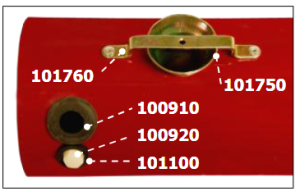
| 100412 | Propane Jet | 100910 | Grommet DA 140/200/40 |
| 100920 | Plastic Insulating Screw | 101100 | Blind Rivet Nut |
| 100750 | Injector | 101131 | Wing nut M6 |
| 101760 | Propane Jet holder |
PURIVOX KARUSSELL-TRIPLEX
construction manual
Purivox Carousel Triplex V
Instruction Manual

Hazard warning – Purivox Carousel Triplex V
 Please read the instruction manual very carefully before using and assembling the unit.
- Using the device indoors is not
- Never point the sound tube in the direction of people or flammable objects, because a small jet flame and a pressure wave will exit the sound
- Note regulations in terms of storage, setting up and arranging the propane gas
- The Purivox Carousel Triplex V is only built for using in the agricultural sector (Proper use)
- Any other use is considered
- For damage resulting from improper use. The manufacturer of the equipment shall not be
- The Purivox Carousel Triplex V may only be used, maintained and repaired by persons over 18 years, who are acquainted with the equipment and informed of
- The relevant accident prevention regulations as well as other generally recognized safety, health rules and regulations must be
- Any modifications to the equipment shall immediately exclude the manufacturer from any liability or resulting
Contents
- Hazard warning
- Contents
- Components – Purivox Carousel Triplex V
- Electronic unit
- Power supply / Batteries
- Timer
- Shot frequency
- Volume
- Number of shots
- Assembly instruction
- Spare parts – Electronic unit
- Spare parts – Purivox Carousel Triplex V
- Troubleshooting
- Optional equipment – Mirror pyramid
Notice:
The gas regulator which is shown on all the pictures in the manual is a German gas regulator type. If you have ordered a unit with a POL gas regulator, the German regulator is replaced with a POL regulator.
Also the gas bottle can look different to the model that you are using.
But always remember to use only certified propane gas bottles.
Components – Purivox Carousel Triplex V
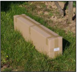
- Sound tube (106040)
- Foot plate big (102273)
- Foot plate small (102275)
- POL gas regulator complete (101660)
- Cain 2m (102080)
- Adjustable pole (102026 & 102028)
- Pole long (102025)
- Pole short (102023)
- Tripod bearing block (102072)
- Cross bar (102090)
- Electronic unit (108510)
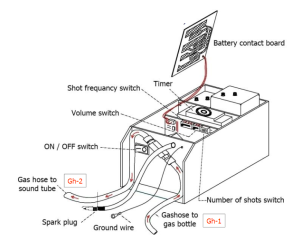
Electronic unit
The controller is in a black weatherproof plastic case.
To get to the operating elements and set up the unit, lift up the lid
Inside of the Electronic unit:
- Battery compartment
- 24 hour Timer
- Switch for shot frequency
- Switch for volume
- Switch for number of shots
Outside of the Electronic unit:
- ON / OFF switch
- Ignition cable with spark plug and ground wire
- Solenoid valve with gas hoses
- Gas hoses (Gh-1 and Gh-2)
Power supply / Batteries
Before working on the batteries or inserting new batteries, make sure that the unit is turned OFF!
The ON / OFF switch is on the front of the electronic unit and is labelled with I for ON and 0 for OFF.
To insert the batteries release the locking by pressing the plastic plate direction the clock. The battery contact board
can then be removed upwards.
Important:
The batteries must be removed when the unit is stored!

Open the lid of the electronic unit (108511) and make sure that the paper strip between the batteries and the contact board is removed.
After this press the battery contact board back down to close it.
Setting the timer
If the batteries are inserted and are in contact with the battery contact board the timer will directly start working
To set up the timer, open the clear cover from the timer.
Setting the actual time
By turning the inner disk clockwise the current time is set to the small arrow.
One turn means one hour.
The little mark on the disc is meant to be the minutes. If the mark shows up it is one hour, to the right 1/4 hour, downwards 1/2 hour and to
the left a 3/4 hour.
Setting the work time
The clock is set from the factory so that it will work 24 hours. All cams are pushed outward. To set the pause time, the cams have to pushed in.
Each cam stands for 30 minutes
Cam outside / Unit works
Cam inside / Break (Unit doesn’t work)
The working time should adjust to suit the local conditions. It is recommended to observe the feeding times of the birds/animals and set the timer to suit.
Council regulations may also need to be observed.
Switch I AUTO 0 always in position “Auto”
Important: NEVER turn the timer anticlockwise!!


Setting the shot frequency
You can choose from 4 different time frames, how long the pause time should be.
The unit will then shoot randomly in that time to avoid habituation effect.
 If the number of birds and wild animals is not large then it is possible to increase the pause time. In our experience, an intensive multi-shot approach with longer pause intervals is much better and more effective than lots of frequent shots.
| Switch Position | Timing Cycles |
| 1 | Break of 2-4 minutes |
| 2 | Break of 4-8 minutes |
| 3 | Break of 8-16 minutes |
| 4 | Break of 16-32 minutes |
The best thing is to start with a setup that bangs not so often.
Only when the number of birds and wild animals is getting bigger then change the switch (for example from 3 to 2) to reduce the pause interval.
Setting the volume
With a switch on the board the volume of the unit can be set in two different volumes
For the full volume the switch has to be on position B, for a reduced volume the switch has to be on A
 Switch position A = Reduced sound level 100m distance approx 90db(A)
Switch position B = Full sound level 100m distance approx 96db(A)

Setting the number of shots
Changing the number of shots only when the unit is turned off!
Wait 15 seconds before turning the unit on again so it can re-set properly.
1 shot = both switches up
2 shots = left up / right down
3 shots = left down / right up
4 shots = both switches down

The recommended number of shots is 3.
Tests have shown that the best results will be made with the 3 shots.
Assembly instruction Purivox Carousel Triplex V
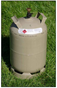 A standard propane gas bottle is required for normal operation. (Not included in delivery)
Notice:
Propane gas bottle can look similar to the one which is shown in the manual.
 Required tools:
Spanner (size 10) or socket wrench (size 10)
and Pliers

 Once the electronic unit is set. Close the lid of the electronic unit and turn the electronic unit over.
Now remove the wing nut, tooth washer and washer.
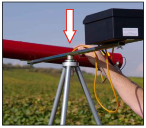
Take the cross bar (102090) and put on end with the hole on the screw.
Once that is done put the washer, toothed washer on the screw and tighten it firmly with the wing nut.
Use the pliers.
 Remove the wing nut, toothed washer and the washer from the thread on the sound tube (106040).
 Once this is done the cross bar will be attached to the sound tube and tightened with the wing nut. Make sure that the cross bar is
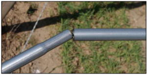
 Make sure that the opening from the sound tube for the spark plug shows in the same direction like the cross bar (see picture)
 Remove the propane nozzle which is plugged into the gas hose (Gh-2) which runs away from the electronic unit.
The propane nozzle will screwed into the nozzle-bracket from the sound tube.

 Now the gas hose is pushed onto the gas nozzle. Make sure that it is the gas hose (Gh-2) which goes away from the electronic unit.
 Unscrew the plastic screw from the thread insert rubber. Take now the plastic screw; slide it onto the ground wire and through the spark plug.
 The spark plug is inserted through the opening of the rubber grommet. Then the plastic screw is screwed into the thread insert rubber and tightened firmly.

The bearing block (102072) will be screwed on the cross bar and tighten carefully by using a screwdriver.
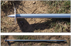
Insert the big foot plates (102273) into the long poles (102025). Make sure to use the long poles. This will prevent that rainwater can run into the poles.
Now the short pole (102023) will be fitted to the long pole.


Take the adjustable pole (102026 & 102028) and put the small foot plate (102275) on. Now hold the previously assembled poles (long + short) next to the adjustable pole. Use the wing screw to adjust the length so that the adjustable pole has the same length like the other poles.
After this place all three poles on the bearing block.

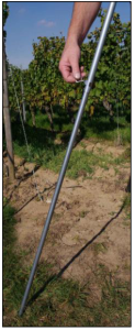
After all poles are mounted on the bearing block, the Purivox Carousel Triplex V can be turned over and put on the foot plates.
 Using the adjustable pole the unit can be adjusted to the ground that the unit stands horizontally.
Slide the gas hose (Gh-2) trough the middle of the bearing block.
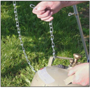
Hang one side of the chain (102080) with the sharp end of the hook pointing out of the bearing block. Move the chain through the handle of the bottle and attach the other end of the chain also to the bearing block (sharp end outside!) Slide the gas hose (Gh-2) trough the middle of the bearing block.

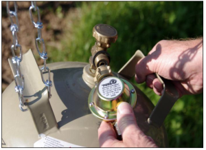
Screw the POL gas regulator (101660) on the propane gas bottle and connect the gas hose from the regulator with the gas hose (Gh-2) of the electronic unit. Take care that the two hoses are moved together completely.


Open the valve of the gas bottle and switch on the unit.
The unit will now start working.
After the unit is switched on move immediately away from the unit!

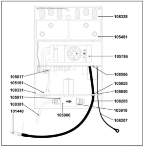
Spare parts – Electronic unit
108511 Electronic unit for Purivox Carousel / Razzo Triplex V
108328 Battery contact board with cable
105481 Battery 6 Volt/7Ah
105786 Timer – Paladin 12 Volt 108506 Circuit board – Uplexa08
105855 Grommet DK 6/9/12-12 PVC
105850 Grommet 2/5/8-2
108206 Ignition cable for Purivox Carousel / Razzo Triplex V
105911 Straight fitting for solenoid valve with filter
108208 Ground wire for Purivox Carousel / Razzo Triplex V
105900 Solenoid complete
101440 Spark plug complete
100381 Gas hose / sold by meter
105910 Straight fitting for solenoid valve conical
108331 Plastic case with lid and spring plungers
105161 ON/OFF switch without cable
105165 ON/OFF switch with cable 105017 6-pin connector with cable

Spare parts – Purivox Carousel Triplex V
108511 Electronic unit V for Purivox Carousel Triplex V
102090 Cross bar
106040 Sound tube
108332 Lid for electronic unit case
100920 Plastic screw M6x20
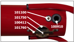
100910 Rubber grommet
103440 POP-blind rivet 3,2×10
101100 Threaded insert rubber M6
100412 Propane nozzle Ms60Pb
102280 Bracket
105016 Rubber buffer for electronics unit
102072 Tripod bearing block complete
102062 Sealing ring 17×4 for tripod bearing block
102061 Protective cover for tripod bearing block
102220 Circlip for steel shaft
102060 Bearing
102052 Tripod bearing block with foot parts 1-3
102054 Clamping spring for tripod bearing block / foot plates
101660 Gas regulator POL with hose, grommet and union nut complete
101610 Gas regulator POL
101570 Tail for regulator
101350 Union nut for regulator 101570 Tail for regulator
100401 Hose spout brass double nipple
102273 Footplate big
102275 Footplate small
101750 Injector
101760 Nozzle bracket
102080 Chain 2m long
106140 Bearing tube
102023 Stand pole short
102025 Stand pole long
102026 Stand pole adjustable out
102028 Stand pole adjustable in
100820 Washer 6,4×18 DIN 9021
100790 Toothed washer I6,4
101131 Wing nut M6
111127 Purivox Carousel Triplex V

Troubleshooting
Purivox Carousel Triplex V doesn´t bang:
- Check the gas bottle capacity; remove the gas hose from the solenoid valve an dip the hose into a bucket of water and open the gas valve.
Smoke or open fire in this situation can be dangerous!
- If the gas bubbles in the water, check the hose for leaks.
- Check the hose connections on the solenoid valves. Is the direction of the gas flow the same as the arrow on the solenoid valve? Don´t kink the hoses.
- Is the propane jet from the jet hose screwed into the injector?
- Battery check: Each battery must have a minimum voltage of 5 volts. Is the transmitter in function? If necessary check the voltage of batteries with a voltmeter in the workshop of your dealer. If the combined voltage has dropped to 9,0 volts, or the short circuit current of the single batteries drops under 1 ampere, replace the batteries.
Notes: If the device is not in use you have to – in order to avoid damage to the electronic units by leaking batteries – remove the batteries mandatory. Close the unit and store it dry.
- Is the time at the timer set correctly? Maybe control.
- Is the outside switch at position “1” ON?
- Spark control. Is the spark cable intact? If the cable is damaged, please don´t fix it by yourself! Warning: High voltage spark! Distance between the electrodes of the ignition spark should be approx 5mm. Test the controller function without gas flow turned on! Hold ignition spark plug holder together with the earth cable to the metal bracket. Don´t touch the spark gap with your fingers while switching the unit ON. Don´t run the earth cable and spark cable next to each other.
- The unit has a self reset security safety Please watch out for potential short circuits between the connecters.
Purivox Carousel Triplex V bangs at times, when it shouldn’t bang.
- Timer is set
- The timer has no internal So after removing the batteries or when the batteries are totally flat, the time must be reset when new batteries are fitted.
Mirror pyramid
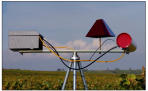
Using the optional mirror pyramid which is mounted on the top of the Purivox Carousel Triplex V adds a strong visual deterrent.
The mirror pyramid is especially made for protecting areas which are close to power lines and big trees. It reflects powerful light beams from the sun which will flash at any birds nearby. These blinding flashes cause the birds to fly off.
With the two different colors on the Pyramid, the scaring effect is reinforced.
The mirror pyramid is mounted on a rod to the crossbar of the Purivox Carousel Triplex V. With the rubber buffer fitted, the pyramid can wiggle. This means with every shot, the pyramid is wiggling and increases the overall effect of the unit.
Order No. : 111135


Spare parts – Electronic unit
108511 Electronic unit for Purivox Carousel / Razzo Triplex V
108328 Battery contact board with cable
105481 Battery 6 Volt/7Ah
105786 Timer – Paladin 12 Volt
108506 Circuit board – Uplexa08
105855 Grommet DK 6/9/12-12 PVC
105850 Grommet 2/5/8-2
108206 Ignition cable for Purivox Carousel / Razzo Triplex V
105911 Straight fitting for solenoid valve with filter
108208 Ground wire for Purivox Carousel / Razzo Triplex V
105900 Solenoid complete
101440 Spark plug complete
100381 Gas hose / sold by meter
105910 Straight fitting for solenoid valve conical
108331 Plastic case with lid and spring plungers
105161 ON/OFF switch without cable
105165 ON/OFF switch with cable
105017 6-pin connector with cable

Spare parts – Purivox Carousel Triplex V
108511 Electronic unit V for Purivox Carousel Triplex V
102090 Cross bar
106040 Sound tube
108332 Lid for electronic unit case
100920 Plastic screw M6x20
100910 Rubber grommet
103440 POP-blind rivet 3,2×10
101100 Threaded insert rubber M6
100412 Propane nozzle Ms60Pb
102280 Bracket
105016 Rubber buffer for electronics unit
102072 Tripod bearing block complete
102062 Sealing ring 17×4 for tripod bearing block
102061 Protective cover for tripod bearing block
102220 Circlip for steel shaft
102060 Bearing
102052 Tripod bearing block with foot parts 1-3
102054 Clamping spring for tripod bearing block / foot plates
101660 Gas regulator POL with hose, grommet and union nut complete
101610 Gas regulator POL
101570 Tail for regulator
101350 Union nut for regulator
101570 Tail for regulator
100401 Hose spout brass double nipple
102273 Footplate big
102275 Footplate small
101750 Injector
101760 Nozzle bracket
102080 Chain 2m long
106140 Bearing tube
102023 Stand pole short
102025 Stand pole long
102026 Stand pole adjustable out
102028 Stand pole adjustable in
100820 Washer 6,4×18 DIN 9021
100790 Toothed washer I6,4
101131 Wing nut M6
111127 Purivox Carousel Triplex V
Spare parts – Electronic unit
108510 Electronic unit for Purivox Triplex V
108328 Battery contact board with cable
105481 Battery 6 Volt/7Ah
105786 Timer – Paladin 12 Volt
108506 Circuit board – Uplexa08
105855 Grommet DK 6/9/12-12 PVC
105850 Grommet 2/5/8-2
108205 Ignition cable for Purivox Triplex V
105911 Straight fitting for solenoid valve with filter
108207 Ground wire for Purivox Triplex V
105900 Solenoid valve complete
101440 Spark plug complete
100381 Gas hose / sold by meter
105910 Straight fitting for solenoid valve conical
108331 Plastic case with lid and spring plungers
105161 ON/OFF switch without cable
105165 ON/OFF switch with cable
105017 6-pin connector with cable
Spare parts – Purivox Triplex V
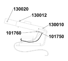 130010 Shot frame with sound tube type 500
100910 Rubber grommet
DA140/200/40 for sound tube 100920 Plastic screw M6x20
101100 Threaded insert rubber M6
101750 Injector
101760 Nozzle bracket
103440 POP-blind rivet 3,2×10
108510 Electronic unit Triplex V
108332 Lid for electronic unit case
100412 Propane nozzle Ms60Pb
105825 Rubber grommet 4/7/10,1,5
105019 A2 screw KA 40×10 for plastic case
101660 Gas regulator POL with hose, grommet and union nut complete
101610 Gas regulator POL
101570 Tail for regulator
101350 Union nut for regulator
100401 Hose spout brass double nipple
101280 Seal washer for regulator
111126 Purivox Triplex V
PURIVOX
TRIPLEX CAROUSEL
Automatically turning animal and bird scaring device. Automatic acoustic scaring device, triple shooter operating on propane gas. The latest model from 2013 has facility to set number of shots from 1-4.
Protected area comprises 4 – 5 hectares.
 Specifications:
Steel megaphone covered with synthetic material. All steel parts are galvanized and painted, therefore corrosion resistant.
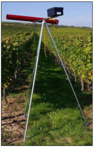
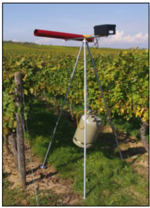
Unit is operated by programmed, electronic control. The electronic parts are built into a sealed box which is resistant to spray water and condensation. This box need not be opened. Megaphone and electronic box is installed on top of a tripod (standard height: 2m). Each shot of the triple-shot aims at a different direction as the rebound turns the megaphone on the rotating beam.
The ignitions are set off by high tension sparks according to the programmed shooting intervals.
There are irregular pauses between the triple-shots. A longer stoppage of the gun can also be programmed and equally be changed again.
The explosion is set off immediately after the gas enters the megaphone – loudness in direction of shot is about
86 dB (A) on 100m distance. This reduces gas consumption to a minimum.
Advantages:
The Triplex Carousel is operation and maintenance free. Once the gun is programmed it will function for months. It need not be put up and taken down daily. Occasional battery and gas replacement is all that is needed.
Due to the triple-shot with irregular intervals between the 3 shots and due to the ever changing shooting direction the birds and animals cannot locate the source of the explosions any longer, and are driven away and kept away.
The Triplex Carousel is cost-saving and economic because of its long life and various application possibilities from time of sowing to the time of harvesting.
Carousel Triplex is an efficient seed and crop protection for a 4 – 5 hectare area. This means an improvement of
your yields.
PURIVOX
TRIPLEX TRIPLE-JOHN
Stationary animal and bird scaring device. Automatic acoustic scaring device, triple shooter operating on propane gas. The latest model from 2013 has facility to set number of shots from 1-4. Protected area comprises 1 – 2 hectares.
Specifications:
Steel megaphone covered with synthetic material. All steel parts are galvanized and painted, therefore corrosion resistant.
Unit is operated by programmed, electronic control.
The electronic parts are built into a sealed box which is resistant to spray water and condensation. This box need not be opened. The ignitions are set off by high tension sparks according to the programmed shooting intervals.
There are irregular pauses between the triple-shots. A longer stoppage of the gun can also be programmed and equally be changed again.
The explosion is set off immediately after the gas enters the megaphone – loudness in direction of shot is about 86 dB(A) on 100m distance. This reduces gas consumption to a minimum.
Advantages:
The Triplex Triple-John is operation and maintenance free. Once the gun is programmed it will function for months. It need not be put up and taken down daily. Occasional battery and gas replacement is all that is needed.
Due to the triple-shot with irregular intervals between the 3 shots the birds and animals cannot locate the source of the explosions and are driven away and kept away.
The Triplex Triple-John is cost- saving and economic because of its long life and various application possibilities from time of sowing to the time of harvesting.
Instruction manual for Remote controlled electronic unit &
Remote controller TX-H1
Instruction Manual
Hazard warning
Using the device indoor is not permitted.
Never point the Sound tube in the direction of people or flammable objects, because since the bang a jet flame and a pressure wave comes out of the sound tube.
Note regulations in terms of storage in setting up and arranging the propane gas bottle.
For damages resulting from not proper use, the manufacturer of the equipment shall not be liable.
The unit may only be used, maintained and repaired by persons over 18 years, who are acquaint with the equipment and informed of the risks.
The relevant accident prevention regulations as well as other generally recognized safety and health rules and regulations must be observed.
All modifications to the equipment shall exclude any liability of the manufacturer for any resulting damages.
Notice!
Always wear hearing protection if you stand in a close distance to the unit!
Remote controlled electronic unit
The remote controlled electronic is very similar to the normal Purivox electronic unit.
The remote controlled has no timer. It will be triggered from the remote controller. With this controller it is possible to control up to 100 units in a distance of 8km (in a line of sight and good weather).
Remote controller
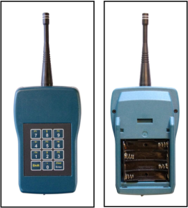
With the remote controller it is possible to control up to 100 units. The range, depends if any objects are between the remote controller and the unit, is up to 8 kilometers.
The remote controller is very easy to use.
The power supply is with 4x Micro AAA 1,5 V batteries. The batteries are inserted at the back of the remote controller.
The frequency of the remote controller is 868 Mhz.
At the bottom of the controller is an ON and OFF switch. The controller has also an automatic energy safe modus, this modus shuts the controller after 1min off if it is not in use.
On the top is a red LED light and inside a speaker to get visual and acoustic feedback.
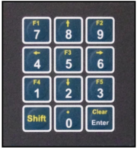 On the keypad are the numbers from 0 – 9, a “Shift” and a “Clear/Enter” button.
Every electronic unit unit has two-digit numbers (00;01;02;..). To send a signal just press the two buttons successively. After pressing the first number a beep will be heard and also the light of the LED will be lighten.
This beep and the light will turn off as soon as the second number is tipped in and the remote controller will send the signal to the unit.
If a wrong button is pressed, just press the “Clear/Enter” button to delete the actual process.
As soon as the battery runs flat and the buttons are pressed and no light or sound came, it is possible to press the “shift” button + the number to send a signal to the unit.
But notice this will only last a few times!
Setting up the electronic unit.
There are a few settings on the unit that can be changed.
- Group setting
- Sound level
- Number of shots
- Group setting
Each unit can be set to a group to control more than one unit at the same time. The group will be set with the switch located on the circuit board in the electronic unit.
- Number 1: No group
- Number 2: Group 2 will be fired with 91
- Number 3: Group 3 will be fired with 92
- Number 4: Group 3 will be fired with 93
- Sound level
The sound level can be changed in 2 steps.
Switch position A =
Reduced sound level100m distance approx 90db(A)
Switch position B =
Full sound level100m distance approx 96db(A)
- Number of shots
The number of shots is setting how often the unit will shot in a sequence. We recommend for bird control 3 shots.
1 shot = both switches up
2 shot = left up / right down
3 shot = left down / right up
4 shot = both switches down
Example
Two units are placed. One unit has the number 05 the other unit the number 10. After switching on the remote controller, press the number “0” on the keypad.
A beep will be heard and the light will turn on, as soon the “5” will be pressed the sound and the light will go off and the unit with the number 05 will bang.
If for any reason, a wrong button will be pressed. For example the unit with the number 10 should bang and the user is pressing the number “4” instead of pressing the number “1” he has just to
press the “Clear/Enter” button to stop the process. After this the light and sound will turn off again and he can start from the beginning with tipping in the number.
For more information or help, contact MECAL P/L.
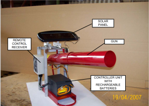
REMOTE CONTROL GUN
Wind-proof-plate for the Purivox Carousel Triplex V
The wind-proof-plate is made out of stainless steel and is for securing the Purivox Carousel Triplex V against strong wind.
For mount the -wpp-to the Carousel, remove the rubber and the protection plate of the bearing block. Push now the -wpp-over the bearing until it is touching the bearing block.
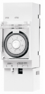
INSTRUCTIONS 2009-2017
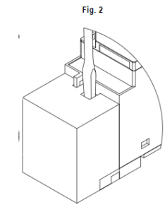
Safety notes / Connection
CZ ČEŠTINA D DEUTSCH
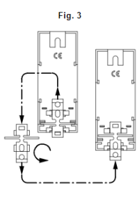
! Montáž a připojení smí provádět jen způsobilý odborný pracovník. Jinak může vzniknout nebezpečí ! Einbau und Montage dürfen nur von einer Elektrofachkraft durchgeführt werden! požáru nebo úrazu elektrickým proudem. Anderenfalls besteht Brandgefahr oder Gefahr eines elektrischen Schlages.
! Zásahy a změny na přístroji vedou ke ztrátě záruky. Elektronika spínacích hodin je chráněna před ! Eingriffe und Veränderungen am Gerät führen zum Erlöschen der Garantie. Die Elektronik dieser vnějšími rušivými vlivy. Při neobvyklém vnějším rušení se však jeho vliv nedá plně vyloučit. Schaltuhr ist gegen Störeinflüsse weitgehend geschützt. Bei außergewöhnlich hoher Störstrahlung
Montáž: Připojení spínacích hodin a spínaných přístrojů na napětí a frekvenci uvedenou na typovém lässt sich eine Beeinflussung jedoch nicht völlig ausschließen.
štítku dle schématu (Fig. 1). Při instalaci sejměte kryt dle obrázku (Fig. 2). Při montáži na stěnu otočte Montage: Anschluss entsprechend der auf dem Typenschild angegebenen Spannung und des zu pružinovou západku dle obrázku (Fig. 3). schaltenden Gerätes (Fig. 1). Für die Installation Klemmenabdeckung entfernen (Fig. 2). Für die
Wandmontage ist die Rastfeder umzudrehen (Fig. 3).
DK DANSK
! Indbygning og montage af elektriske apparater må kun foretages af elektroinstallatører
! Kontakturets er I stort omfang sikret mod elektrisk støj, Ved usædvanlig kraftig støj kan påvirkning ikke helt udelukkes
Tilslutningsskema: Tilslut ifølge mærkeskilt spænding og frekvens, som på tilslutningsskemaet.
E ESPAŇOL
! La instalación y montaje de equipos eléctricos se debe llevar a cabo solamente por personal especializado! De lo contrario hay riesgo de incendio o electrocución.
! Cualquier manipulación del interior del producto no autorizada anula la garantia del mismo. El circuito electrónico está protegido contra una amplia gama de influencias externas. Si estas influencias superan determinados límites, pueden producirse funcionamientos incorrectos del interruptor horario.
Conexión: Conectar el componente según el esquema indicado en el producto.
F FRANÇAIS FIN SUOMI
! l’installation et le montage d’appareils électriques ne doivent être effectués que par des électriciens. ! Sähkölaitteen kokoonpano ja asennus tulee jättää valtuutetulle sähkömiehelle.
Sinon il y a danger d´ incendie ou danger de choc électrique. Muussa tapauksessa on sähköiskun tai tulipalon vaara!
! La garantie devient caduque en cas de mauvaises manipulations ou de modifications de l’appareil. ! Takuu raukeaa jos kotelo avataan! Laitteen elektroniikka on suojattu monilta ulkoisilta häiriöiltä.
L’électronique de l’appareil est protégé dans une large mesure contre les perturbations. Malgré tout, si Suuret häiriöt saattavat kuitenkin aiheuttaa virhetoimintoja.
ces perturbations sont importantes, on ne peut pas exclure un dysfonctionnement de l’appareil. Liitännät: Tarkista ja kytke syöttöjännite kytkentäkaavion mukaisesti huomioiden mahdollisten
Mise en service: Installer l’appareil selon le schéma de raccordement donné sur le produit. lisälaitteiden kytkentäkaaviot.
GB ENGLISH
! The installation and assembly of electrical equipment must only be carried out by skilled personnel.
Otherwise the dangers of fire or electric shock may result.
! Warranty void if housing opened by unauthorised person. The internal electronic circuit is protected against a wide range of external influences. However, incorrect operating may occur if external influences are excessive.
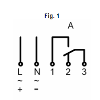
Connections: Connect the supply voltage/frequency (as stated on the Time-Switch label) to terminals L &
N. Connect the appliance to be controlled through the appropriate volt-free contacts, in accordance with the requirements of the appliance.
H MAGYAR
! Az elektromos eszközöket csak szakember szerelheti össze és építheti be! Ellenkező esetben tűzveszély és áramütés veszélye áll fenn.
! A készülék belsejének szétszerelése vagy megváltoztatása esetén a garancia nem érvényes. A kapcsolóóra elektronikája messzemenően védett a zavaró hatásokkal szemben. Rendkívül nagy- mértékű zavaró sugárzás esetén azonban nem zárható ki a készülék meghibásodása.
Szerelési tudnivalók: A kapcsolóórát a bekötési rajz (Fig.2) szerint csatlakoztassuk az adattábla szerinti feszültségű és frekvenciájú hálózatra és kössük be a kapcsolandó terhelést. Falra történő szereléshez a rugós műanyag részt fordítsuk meg (Fig.3)
I ITALIANO N NORSK
! L’installazione ed il montaggio delle apparecchiature elettriche deve essere eseguito solo da ! Installasjon/montering må kun utføres av autorisert installatør. Ellers kan det føre til brannfare eller personale esperto. Esiste un pericolo di infiammabilità e/o shock elettrico. fare for elektrisk sjokk.
! Manomissioni o modifiche non autorizzate dell’apparecchio comportano l’estinzione della garanzia. Il ! Elektronikken i dette koplingsuret er støybeskyttet.
circuito elettronico del prodotto è protetto contro un’ampia gamma di disturbi. Tuttavia se questi Koplingsskjema: Apparatet må kun tilkoples spenning og frekvens som anvist på apparatet. disturbi sono di entità molto elevata, potrebbe verificarsi un malfunzionamento del prodotto.
Schema di collegamento: Collegare l’apperecchio secondo lo schema di collegamento indicato sul prodotto (Fig.1).
NL NEDERLANDS
! Inbouw en montage dient door elektrotechnische vakmensen te geschieden. Anders ontstaat brandgevaar of het gevaar van een elektrische schok.
! Door openen en veranderingen aan de schakelklok vervalt de garantie. De elektronica van deze schakelklok is tegen storingsinvloeden beveiligd. Bij uitzonderlijk intensieve stoorsignalen is beïnvloeding echter niet uitgesloten.
Aansluitschema: Sluit de spanning/frequentie aan volgens het typeplaatje overeenkomstig de aansluitgegevens voor deze tijdschakelklok en de te schakelen apparatuur.
P PORTUGUES
! A instalação e montagem dos equipamentos elétricos devem ser realizadas somente por pessoal especializado. Atentar ao risco de incêndio ou de descarga elétrica.
! Qualquer intervenção não autorizada no interior do produto anula a garantia do mesmo. O circuito elétrico está protegido contra uma ampla variedade de influências externas. Se estas influências superarem determinados limites, as mesmas podem produzir funcionamentos incorretos no programador horário.
Ligação: Conectar a alimentação (tensão/frequência) como indica a etiqueta de características do produto, de acordo com os esquemas de ligação do programador horário e do aparelho elétrico a ser controlado.
POLSKI RO ROMÂNĂ
! Instalacja i montaż urządzeń elektrycznych musi być przeprowadzana wyłącznie przez ! Instalarea şi montarea echipamentului electric trebuie realizată numai de persoane calificate! În caz wykwalifikowanego pracownika! W przeciwnym razie grozi pożarem lub porażeniem prądem. contrar, poate apare pericol de incendiu sau de electrocutare.
! Montaż zegara przez osobę niewykwalifokowaną grzozi utratą gwarancji. Nieprawidłowe działanie ! Garanţia produsului se pierde în cazul desfacerii carcasei de către persoane neautorizate. Circuitul może wystąpić kiedy zakłócenia przekroczą dopuszczalne limity! electronic este protejat împotriva unei game largi de factori externi. Dacă limitele admise ale
Montaż: Podłącz zasilanie (parametry podane na etykiecie) zgodnie z rysunkiem (Fig.1), odbiornik infuenţelor externe sunt depăşite se poate ajunge la o funcţionare incorectă a programatorului. podłącz zgodnie z opisem na rysunku (Fig.2). Przed rozpoczęciem podłączenia zdejmij obudowę zgodnie Conexiunile: Alimentarea (tensiune / frecvenţă) trebuie să fie în concordanţă cu: parametrii indicaţi pe
z rysunkiem (Fig.3). eticheta produsului, cu detaliile de conexiune prezentate pentru acest tip de programator în figura (Fig.1) şi cu aplicaţiile ce urmează a fi comandate de ceasul programabil. Pentru instalare, se îndepărtează capacul cutiei de cleme (Fig.2). Pentru montajul pe perete, se roteşte resortul cu clichet (Fig.3).
RUSSKIJ
! Установка и сборка электрического оборудования должна осуществляться только квалифицированным лицом! В противном случае существует опасность возникновения пожара, либо поражения электрическим током.
! Гарантия недействительна в том случае, если корпус устройства был вскрыт неквалифицированным лицом. Электронная схема защищена от внешних воздействий. При нарушении условий эксплуатации, возможна неправильная работа устройства.
Подключение: Подключение устройства к сети следует осуществлять в соответствии с техническими данными, указанными на этикетке и на корпусе. Перед подключением следует снять крышку с клемм (Fig.2). При монтаже устройства на DIN-рейку, смотрите схему (Fig.3).
S SVENSKA
! Montage och inkoppling skall utföras av behörig elektriker! Annars finns risk för bramd eller elektriskt överslag
! Ingrepp och ändringar på uret förverkar garantin. Elektroniken i kopplingsuret är störningsskyddat.
Vid onormalt hög störningsstrålning kan påverkan dock inte uteslutas.
Inkopplingsanvisning: Anslut enligt på typskylten angiven spänning och frekvens, lika anslutningsbilden för kopplingsuret och ansluten apparat.
SK SLOVENSKO
! Stavba a montáž elektrických prístrojov je povolená len elektroodborníkom!
! Zásahy a zmeny v prístroji vedú k vymazaniu garancie. Elektronika týchto spínacích hodín je chránená proti rušivým vplyvom. Pri obyčajnom vonkajšom vysokom rušivom žiarení sa nedá úplne zabrániť vplyvu.
Koncovkový obrázok: Koncovka, podľa zadaného rozpätia a frekvencie na typovom štítku, zodpovedajúca koncovkovému obrázku pre tieto spínacie hodiny a tie k spínaným prístrojom.
Adjustments
CZ ČEŠTINA D DEUTSCH
Nastavení spínacích programů = Fig. A Schaltprogramm einstellen = Fig. A
AUTO výstup je spínán dle zadaného programu AUTO Der Ausgang schaltet nach dem eingestellten Programm
I výstup je trvale sepnut I Dauer-EIN des Ausgangs
výstup je trvale rozepnutý Dauer-AUS des Ausgangs
Nastavení času = Fig. B Uhrzeit einstellen = Fig. B
Nastavení času spínání pomocí číselníku [po směru hodinových ručiček]. Einstellen der Tageszeit durch Drehen des zentralen Drehknopfes (des
Spínací hodiny se zálohou chodu Minutenzeigers) im Uhrzeigersinn!
Záloha chodu při výpadku napájení cca 100 hodin. Schaltuhren mit Gangreserve
Bei Spannungsunterbrechung läuft die Zeitschaltuhr ca. 100 h weiter
DK DANSK
Indstilling af program = Fig. A
AUTO Kanalen skifter ifølge det indstillede program I Konstant ON [Kanalen skifter til konstant ON] Konstant OFF
Indstilling af ur = Fig. B
Man indstiller tiden ved at dreje til højre på minutviseren [med uret]
Kontaktur med gangreserve
Uret køre uden spænning I ca. 100 timer E ESPAŇOL
Programación = Fig. A
AUTO El relé conecta de acuerdo con el progama seleccionado con los caballetes
I Conectado permanente
Desconectado permanente
Puesta en hora = Fig. B
Puesta en hora: Girar la aguja de minutos [en sentido horario].
Interruptores horarios con reserva de marcha
En caso de corte de la alimentación el interruptor horario mantendrá la función durante 100 horas aproximadamente
F FRANÇAIS
Affichage du programme = Fig. A
AUTO La commutation du contact se fait selon le programme affiché I Marche forcée [Le contact est en position ON en permanence] Sortie en arrêt continu
Réglage de l’heure = Fig. B
Mise à l´heure par rotation en sens horaire de l´aiguille des minutes [ seulement dans le sens des aiguilles d’une montre].
Réserve de marche
l’interrupteur avec réserve fonctionne normalement sans alimentation pendant environ 100H. FIN SUOMI
Kytkentäaikojen asetus = Fig. A
AUTO Lähtö kytkeytyy automaattisesti osoittimilla valittuun aikaan
I On [Lähtö on päällä] Off
Kellonajan asetus = Fig. B
Aseta oikea aika kääntämällä minuuttiosoitinta [vuonna myötäpäivään].
Varakäynti
Sähkökatkon varalta kellokytkimessä on 100 tunnin varakäynti.
GB ENGLISH
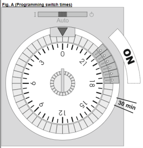
Programming switch times & selecting the switching program = Fig. A
AUTO The output will switch according to the program as determined by the position of the tappets
I Permanently On: The output is always on. Permanently Off: The output is always off
Setting the current time of day = Fig. B
Each complete revolution of the central knob will advance the time by one hour (each incremental click = 1minute). Only turn clockwise!!
Time Switches with reserve
During a supply interruption the time switch will continue to run for approximately 100 hours, provided it has been powered for the previous 36 hours.
H MAGYAR
Kapcsolóprogram beállítása = Fig. A
AUTO A kimeneti záróérintkező a beállított program szerint kapcsol
I Állandóan BE (a kimeneti záróérintkező állandóan zárt) Állandóan KI (a kimeneti záróérintkező állandóan nyitott)
Órabeállítás = Fig. B
Az aktuális időt a percmutató forgatásával állítsuk be [az óramutató irányában].
Tartalékos kapcsolóórák
Áramkimaradás esetén az óra még kb. 100 óráig tovább megy
I ITALIANO N NORSK
Impostazione del programma = Fig. A Programmering av koplingstidspunkter = Fig. A
AUTO La commutazione del contatto avviene secondo il programma AUTO Utgangsreleet følger programmet algt ved segmentenes stillinger impostato I Permanent PÅ: Utgangsreleet ligger konstant PÅ
I Perm ON: Il contatto è in posizione permanente ON Permanent AV: Utgangsreleet ligger konstant AV Perm OFF: Il contatto è in posizione permanente OFF Programmering av aktuell tid = Fig. B
Regolazione dell’ora = Fig. B Tiden innstilles ved å dreie minuttviseren [med uret].
Impostazione dell’ora mediante rotazione dell’ indicatore dei minuti Tidsur med batteri back-up (gangreserve)
[in senso orario]. Ved strømbrudd fortsetter uret å gå i ca. 100 timer
Riserva di carica: Interruttore orario con Riserva
Funziona regolarmente senza alimentazione per circa 100 ore, dopo 36 ore di alimentazione continua
NL NEDERLANDS
Schakelprogramma instellen = Fig. A
AUTO De uitgang schakelt volgens het ingestelde programma
I Continu-IN van de uitgang Continu-UIT van de uitgang
Tijd instellen = Fig. B
Van de actuele tijd: door de minutenwijzer te draaien [met de klok mee].
Schakelklokken met gangreserve
De gangreserve na spanningsonderbreking is ca. 100 uur P PORTUGUES
Programação = Fig. A
AUTO A comutação dos contatos dá-se segundo o programa selecionado
I Permanentemente Ligado (ON)
Permanentemente Desligado (OFF)
Introduzir hora atual = Fig. B
Programação diária: Por rotação do disco dos minutos no sentido horário [em sentido horário].
Interruptores Horários com reserva de movimento
Durante uma interrrupção da alimentação, o programador horário funciona por aproximadamente 100 horas
POLSKI
Ustawienie programu łączeń = Fig. A
AUTO Wyjscie przekaźnikowe – zgodnie z ustawionym przełącznikiem
I Zawsze załączony: wyjście zawsze zał. Zawsze wyłączony: wyjście zawsze wył.
Aktualny czas = Fig. B
Nastawy czasu rzeczywistego przy pomocy pokrętła minutowego [Tylko zgodnie z ruchem wskazówek zegara].
Rezerwa czasowa
Po zaniku napięcia zegar ma podtrzymanie na 100h RO ROMANA
Programarea funcţionării = Fig. A
AUTO Contactul de la ieşirea programatorului este în concordanţă cu programul selectat prin intermediul tijelor de comandă
I Contact anclanşat – ON permanent Contact declanşat – OFF permanent
Reglarea orei curente = Fig. B
Setarea orei curente se face prin rotirea manuală a minutarului [în sensul acelor de ceas].
Rezerva (autonomia)
În cazul întreruperii tensiunii de alimentare (de la reţea), datorită rezervei programul va mai rula pentru o perioadă de aproximativ 100h (ore)
RUSSKIJ
Установка таймера = Fig. A
AUTO Контакт переключается в зависимости от программы, выбранной с помощью поворотной шкалы
I Постоянно ВКЛ.: Контакт нормально закрытый Постоянно ВЫКЛ.: Контакт нормально открытый
Установка времени срабатывания = Fig. B [по часовой стрелке] Резерв
При перерыве питания, реле времени продолжает работать еще приблизительно 100 часа S
SVENSKA
Ställa in kopplingsprogram = Fig. A
AUTO Kanalen kopplas enligt inställt program.
I Till Kanalen är kontinuerligt till Från Kanalen är kontinuerligt av
Tidsinställning = Fig. B
Ställ in aktuell tid genom att vrida runt minutvisaren [medsols].
Kopplingsur med gångreserv
Uret går i ca 100 timmar om strömmen bryts
SK SLOVENSKO
Nastavenie spínacieho programu = Fig. A
AUTO Kanál zapnúť podľa nastaveného programu I Permanent-ON [Kanál ide do trvania ZAP] Permanent-OFF
Nastavenie hodinového času = Fig. B [V smere hodinových ručičiek] Poznámka: Rezerva chodu pri prerušení prúdu. Hodiny bežia ca. 100 hod. ďalej