Description
 MECAL -JET
DUST CONTROL SYSTEM
THE ONLY SYSTEM ENGINEERED FOR EFFECTIVE, LOW COST CONTROL OF DUST AT ITS SOURCE.
 MECAL-JET SUPPRESSES DUST BEFORE IT BECOMES AIRBORNE
Mecal-Jet systems control dust instead of collecting it. With Mecal-Jet, dust never becomes a problem because it is stopped at the source.
MECAL-JET ELIMINATES NEED FOR EXTENSIVE COLLECTION EQUIPMENT
Any “dry” or mechanical system involves the use of dust bins, bags, ducts, hoods and large motors not required by Mecal-Jet.
 MECAL-JET ELIMINATES TIME & COSTS OF EXTENSIVE SERVICING All equipment used in dry collecting systems must be regularly and periodically cleaned, and the dust disposed of. By doing away with collection, Mecal- Jet reduces maintenance time and costs involved – pays off in low operating costs.
MECAL-.JET SOLVES “IMPOSSIBLE” DUST PROBLEMS
Where dust-producing areas are large and unconfined, Mecal-Jet is the only practical and economical means of controlling dust . . . does no t require the use of elaborate enclosure s or duct work.
MECAL-JET ADDS LESS THAN 1% MOISTURE Using Compound MDS (one part MDS to 4,000 parts water or more), which is one of the most powerful surface active compounds known, Mecal-Jet adds as little as ½ of 1% total moisture for effective dust suppression.
MECAL-JET TREATED MATERIALS HAVE CARRY-OVER ADVANTAGES
Properly applied, Compound MDS provides carry-over dust control through handling, storage and reclaim.
Mecal-Jet has proven it is the only practical method to control dust with an efficiency of 90% plus, from truck dumper area to primary crusher to stockpile and reclaim. Mecal-Jet systems also meet all stat e and local air pollution control codes.
(0 0 0 -0 1 -00 1 /9811)
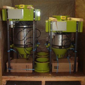
MECAL-JET PROPORTIONERS
 Automatically proportions Compound MOS and water are available in several standard types and capacities or specific designs for specific requirements.
| MODEL | PROPORTIONERS |
| D T | Small capacity – S0L/M Medium capacity – S00L/M Large capacity – 3000 TPH |
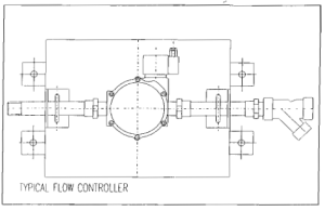 SPRAY JET CONTROLLER
Each spray jet header in the system has a controller which governs the flow of solution supplied by the proportioner. Valve action is positive, either fully on or fully off. Prevents waste of solution; the spray jets are operative only when material is actually flowing.
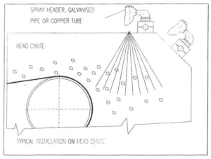
 SPRAY JET HEADER
The spray jet header carries the spray jets which apply the mixed solution to the material. One or more headers are placed at each treatment point, the exact arrangement being determined by the type of spray pattern – selected and the dust control effect required.
 CONTROL ACTUATORS
Automatically detect presence of material to be sprayed and transmit signal to spray jet controller. Standard models are available that operate on mechanical displacement, weight, mass proximity or electrical interlock.
CONTROL PANEL
The Control Panel gives maximum flexibility of the system allowing individual treatment points to be controlled depending on climatic or material condition.
HAURAKI QUARRY, NEW ZEALAND DUST SUPPRESSION SYSTEM 
PRIMARY CRUSHER. 

Before MECAL-JET it was not possible to see this crusher because of the dust. 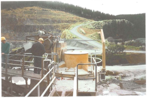
Underbelt Switch 
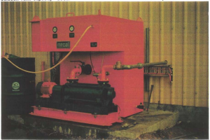
Proportioner Tank and Pump 
MACKAY SUGAR, COAL HANDLING -100TPH 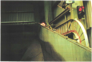 Receiving Hopper (Surface Charger) 1.1 Proportioning Unit
| Solution Pump Capacity – 12000L/hr. @ 700 kPa. | MDS Compound – 205L |
| Compound Pump Capacity – 2.66L/hr, set @ 0.28/hr. | Water Supply Required – 1200L/hr @200 kPa |
| Motor – 4KW, 1450 RPM. | Compound Ratio – 4000 parts |
| Solution Tank Capacity – 800L. | Water: 1 part M.D.S. |
 Proportioning Unit 1.2 Areas of Application
| a) | Surface Charger | 13 Sprays with DS-76 Tips | 9600L/hr. |
| b) | Vibrating Feeder C! | 2 Sprays with DS-66 Tips | 200L/hr. |
| c) | Head Chute Converyor C1 | 2 Sprays with DS-66 Tips | 200L/hr. |
| (Optional) | |||
| d) | Concrete Hopper C2 | 4 Sprays with DS-66 Tips | 400l/hr. |
| e) | Feed Chute C2 | 2 Sprays with DS-66 Tips | 200l/hr. |
| f) | Emergency Hopper C2 | 6 Sprays with DS-66 Tips | 1300L/hr. |
(D00-10-006/9603) 

PART CIRCLE IMPACT SPRINKLERS /35 PJ SERIES

35 PJ -TNT
¾” male bearing. TNT only. Cast bronze body, trips and Precision Jet ” PJ” arm with brass tube, which eliminates arm side splash. Brass bearing sleeve, nipple and straight bore nozzle. Stainless steel arm spring, trip spring and trip collars. Stainless steel slip trip pin (capable of full or part circle operation as desired). Full circle operation obtained by sliding the trip pin up.

35 PJ ADJ-TNT
¾” male bearing. TNT only. Cast bronze body, trips, and Precision Jet “PJ” arm with brass tube, which eliminates arm side splash. Brass bearing sleeve and nipple and adjustable brass nozzle. Nozzle has a stainless steel adjusting pin and spring for control of stream break up. Stainless steel arm spring, trip spring and trip collars. Stainless steel slip trip pin (capable of full or part circle operation as desired). Full circle operation obtained by sliding the trip pin up.

35 PJ DA-TNT
¾” male bearing. TNT only. Cast bronze body, trips and Precision Jet “PJ” arm with brass tube, which eliminates arm side splash. Brass bearing sleeve and nipple and a distance control nozzle to allow adjustment of radius down to 9 m. Nozzle is brass with a stainless steel deflector. Stainless steel arm spring, trip spring and trip collars. Stainless steel slip trip pin ( capable of full or part circle operation as desired). Full circle operation obtained by sliding trip pin up.
| Nozzle Pressure(Bars)+ 100kPa | NOZZLE 5/32″ – 3.6mm | NOZZLE 11/64″ – 4.36mm | NOZZLE 3/16″ – 4.76mm | NOZZLE 13/64″ – 5.16mm | NOZZLE 7/32″ – 5.55mm | ||||||||||
| M | M3/h | L/s | M | M3/h | L/s | M | M3/h | L/s | M | M3/h | L/s | M | M3/h | L/s | |
| 2.0 | 12.8 | 0.86 | 0.24 | 13.0 | 1.04 | 0.29 | 14.0 | 1.22 | 0.34 | 14.0 | 1.45 | 0.40 | 14.6 | 1.69 | 0.47 |
| 2.5 | 13.2 | 0.96 | 0.27 | 13.5 | 1.17 | 0.33 | 14.6 | 1.39 | 0.39 | 14.6 | 1.64 | 0.46 | 15.0 | 1.91 | 0.53 |
| 3.0 | 13.5 | 1.05 | 0.29 | 13.9 | 1.27 | 0.35 | 15.1 | 1.53 | 0.43 | 15.1 | 1.81 | 0.50 | 15.5 | 2.10 | 0.58 |
| 3.5 | 13.8 | 1.14 | 0.32 | 14.3 | 1.37 | 0.38 | 15.5 | 1.64 | 0.46 | 15.5 | 1.94 | 0.54 | 15.9 | 2.25 | 0.63 |
| 4.0 | 14.0 | 1.22 | 0.34 | 14.6 | 1.47 | 0.41 | 15.9 | 1.75 | 0.49 | 15.9 | 2.06 | 0.57 | 16.3 | 2.38 | 0.66 |
PART CIRCLE IMPACT SPRINKLERS 65 SERIES

65 PJ ADJ-TNT
Same as 65 PJ -TNT except has adjustable brass nozzle with stainless steel adjusting pin spring for control of stream break-up.
65 PJ-TNT
1″ female TNT BSP. Cast bronze body, bearing sleeve, trips and Precision Jet (“PJ”) arm with brass tube, which eliminates arm side splash. Brass bearing nipple and straight bore range nozzle. Stainless steel arm spring, trip spring and trip collars. Stainless steel slip trip pin (capable of full or part circle operation as desired). Full circle operation obtained by sliding trip pin up.
M = Radius in meters
| Nozzle Pressure(Bars)+ 100kPa | NOZZLE 7/32″ – 5.55mm | NOZZLE 1/4 – 6.35mm | NOZZLE 9/32″ – 7.14mm | NOZZLE 5/16″ – 7.93mm | NOZZLE 11/32″ – 8.73mm | NOZZLE 3/8″ – 9.2mm | ||||||||||||
| M | M3/h | L/s | M | M3/h | L/s | M | M3/h | L/s | M | M3/h | L/s | M | M3/h | L/s | M | M3/h | L/s | |
| 3.00 | 16.0 | 2.09 | 0.58 | 16.7 | 2.73 | 0.76 | 17.6 | 3.46 | 0.96 | 18.4 | 4.21 | 1.17 | 18.9 | 5.01 | 1.39 | 19.6 | 5.80 | 1.61 |
| 3.50 | 16.8 | 2.26 | 0.63 | 17.4 | 2.96 | 0.82 | 18.4 | 3.75 | 1.04 | 19.3 | 4.57 | 1.27 | 19.9 | 5.45 | 1.51 | 20.6 | 6.32 | 1.75 |
| 4.00 | 17.4 | 2.42 | 0.67 | 17.6 | 3.17 | 0.88 | 19.4 | 4.02 | 1.12 | 20.2 | 4.91 | 1.36 | 20.8 | 5.85 | 1.62 | 21.9 | 5.80 | 1.89 |
| 4.50 | 18.0 | 2.58 | 0.72 | 18.9 | 3.37 | 0.94 | 20.5 | 4.27 | 1.19 | 21.1 | 5.23 | 1.45 | 21.4 | 6.23 | 1.73 | 22.6 | 7.25 | 2.01 |
| 5.00 | 18.6 | 2.72 | 0.76 | 19.4 | 3.56 | 0.99 | 21.5 | 4.51 | 1.25 | 21.9 | 5.54 | 1.54 | 22.2 | 6.59 | 1.83 | 23.0 | 7.68 | 2.13 |
| 5.50 | 19.2 | 2.86 | 0.79 | 19.8 | 3.74 | 1.04 | 21.9 | 4.74 | 1.32 | 22.8 | 5.83 | 1.62 | 23.1 | 6.94 | 1.93 | 23.5 | 8.10 | 2.25 |

85E-TNT/85EW-TNT Series
Widely used as an end gun on center pivot machines. Throw is increased substantially under windy conditions because this model has a non-clog vane. Full or part circle operation. Wide range of nozzles sizes extends application of this series. 85EW-TNT gives lower precipitation rates with plug in place of spreader nozzle. 1 1/4″ male BSP bearing (32mm) PERFORMANCE FOR 85 E-TNT Highest point of stream is 4.2m above nozzle*.
| Nozzle Pressure(Bars)+ 100kPa | NOZZLE 11/32″ x 7/32″ 20°- 8.73mm x 5.55mm | NOZZLE 3/8″ x 7/32″ 20°- 9.52mm x 5.55mm | NOZZLE 13/32″ x 7/32″ 20°- 10.3mm x 5.55mm | NOZZLE 7/16″ x 7/32″ 20°- 11.1mm x 5.55mm | NOZZLE 15/32″ x 7/32″ 20°- 11.9mm x 5.55mm | NOZZLE 1/2″ x 1/4″- 12.7mm x 6.35mm | NOZZLE 17/32″ x 1/4″- 13.4mm x 6.35mm | NOZZLE 9/16″ x 1/4″- 14.2mm x 6.35mm | NOZZLE 5/8″ x 1/4″- 15.8mm x 6.35mm | ||||||||||||||||||
| M | M3/h | L/s | M | M3/h | L/s | M | M3/h | L/s | M | M3/h | L/s | M | M3/h | L/s | M | M3/h | L/s | M | M3/h | L/s | M | M3/h | L/s | M | M3/h | L/s | |
| 3.50 | 22.3 | 7.60 | 2.11 | 23.0 | 8.63 | 2.40 | 24.2 | 9.64 | 2.68 | 24.8 | 10.72 | 2.98 | 25.7 | 11.88 | 3.30 | 26.6 | 13.96 | 3.88 | 26.6 | 15.06 | 4.18 | 28.7 | 16.74 | 4.65 | 29.7 | 19.73 | 5.48 |
| 4.00 | 23.2 | 8.16 | 2.27 | 23.8 | 9.27 | 2.57 | 25.1 | 10.36 | 2.88 | 25.8 | 11.50 | 3.19 | 26.6 | 12.75 | 3.54 | 27.5 | 14.96 | 4.16 | 27.5 | 16.16 | 4.49 | 29.4 | 17.94 | 4.98 | 30.5 | 21.17 | 5.88 |
| 4.50 | 24.1 | 8.68 | 2.41 | 24.7 | 9.87 | 2.74 | 25.6 | 11.04 | 3.87 | 26.5 | 12.24 | 3.40 | 27.4 | 13.57 | 3.77 | 28.4 | 15.90 | 4.42 | 28.4 | 17.18 | 4.77 | 30.2 | 19.08 | 5.30 | 31.1 | 22.52 | 6.25 |
| 5.00 | 24.8 | 9.18 | 2.55 | 25.4 | 10.43 | 2.90 | 26.4 | 11.69 | 3.25 | 27.3 | 12.34 | 3.59 | 28.0 | 14.34 | 3.98 | 29.0 | 16.78 | 4.66 | 29.0 | 18.18 | 5.04 | 30.9 | 20.15 | 5.60 | 31.9 | 23.80 | 6.61 |
| 5.50 | 25.3 | 9.65 | 2.68 | 26.2 | 10.98 | 3.05 | 27.1 | 12.30 | 3.42 | 28.0 | 13.61 | 3.78 | 28.6 | 15.08 | 4.19 | 29.5 | 17.63 | 4.90 | 29.5 | 19.09 | 5.30 | 31.2 | 21.19 | 5.89 | 32.6 | 25.02 | 6.95 |
| 6.00 | 26.0 | 10.11 | 2.81 | 26.8 | 11.50 | 3.19 | 27.7 | 12.90 | 3.58 | 28.6 | 14.25 | 3.96 | 29.4 | 15.79 | 4.39 | 30.3 | 18.44 | 5.12 | 30.3 | 19.98 | 5.55 | 32.1 | 22.18 | 6.16 | 33.2 | 26.18 | 7.27 |
| 6.50 | 26.5 | 10.55 | 2.93 | 27.4 | 12.00 | 3.33 | 28.3 | 13.46 | 3.74 | 29.2 | 14.86 | 4.13 | 29.8 | 16.47 | 4.57 | 30.7 | 19.21 | 5.34 | 30.7 | 20.83 | 5.79 | 32.8 | 23.13 | 6.42 | 33.8 | 27.31 | 7.59 |
| 7.00 | 26.9 | 10.97 | 3.05 | 27.8 | 12.48 | 3.47 | 28.7 | 14.01 | 3.89 | 29.7 | 15.45 | 4.29 | 30.3 | 17.13 | 4.76 | 31.2 | 19.96 | 5.54 | 31.2 | 21.66 | 6.02 | 33.3 | 24.04 | 6.68 | 34.2 | 28.39 | 7.89 |
PERFORMANCE FOR 85 EW-TNT Highest point of stream is 4.2m above nozzle*.
| Nozzle Pressure(Bars)+ 100kPa | NOZZLE 11/32″ – 8.73mm | NOZZLE 3/8″ – 9.52mm | NOZZLE 13/32″ – 10.3mm | NOZZLE 7/16″ – 11.1mm | NOZZLE 15/32″ – 11.9mm | NOZZLE 1/2″ – 12.7mm | NOZZLE 17/32″ – 13.4mm | NOZZLE 9/16″ – 14.2mm | NOZZLE 5/8″ – 15.8mm | ||||||||||||||||||
| M | M3/h | L/s | M | M3/h | L/s | M | M3/h | L/s | M | M3/h | L/s | M | M3/h | L/s | M | M3/h | L/s | M | M3/h | L/s | M | M3/h | L/s | M | M3/h | L/s | |
| 3.50 | 22.3 | 5.58 | 1.55 | 23.0 | 6.61 | 1.84 | 24.2 | 7.62 | 2.12 | 24.8 | 8.70 | 2.42 | 25.7 | 9.87 | 2.74 | 26.6 | 11.01 | 3.06 | 27.5 | 12.11 | 3.36 | 28.7 | 13.78 | 3.83 | 29.7 | 16.78 | 4.66 |
| 4.00 | 23.2 | 5.95 | 1.65 | 23.8 | 7.06 | 1.96 | 25.1 | 8.16 | 2.27 | 25.8 | 9.33 | 2.59 | 26.6 | 10.57 | 2.93 | 27.5 | 11.89 | 3.28 | 28.4 | 13.00 | 3.61 | 29.4 | 14.80 | 4.11 | 30.5 | 17.99 | 5.00 |
| 4.50 | 24.1 | 6.30 | 1.75 | 24.7 | 7.49 | 2.08 | 25.6 | 8.66 | 2.41 | 26.4 | 9.91 | 2.75 | 27.4 | 11.23 | 3.12 | 28.4 | 12.54 | 3.48 | 29.3 | 13.84 | 3.84 | 30.2 | 15.77 | 4.38 | 31.1 | 19.13 | 5.31 |
| 5.00 | 24.8 | 6.62 | 1.84 | 25.4 | 7.89 | 2.19 | 26.4 | 9.14 | 2.54 | 27.3 | 10.47 | 2.91 | 28.0 | 11.85 | 3.29 | 29.0 | 13.25 | 3.68 | 30.0 | 14.63 | 4.06 | 30.9 | 16.68 | 4.63 | 31.9 | 20.21 | 5.61 |
| 5.50 | 25.3 | 6.93 | 1.93 | 26.2 | 8.27 | 2.30 | 27.1 | 9.60 | 2.67 | 28.0 | 11.01 | 3.06 | 28.6 | 12.44 | 3.46 | 29.5 | 13.92 | 3.87 | 30.8 | 15.39 | 4.28 | 31.7 | 17.55 | 4.88 | 32.6 | 21.24 | 5.90 |
| 6.00 | 26.0 | 7.23 | 2.01 | 26.8 | 8.63 | 2.40 | 27.7 | 10.03 | 2.79 | 28.6 | 11.51 | 3.20 | 29.4 | 13.01 | 3.61 | 30.3 | 14.56 | 4.04 | 31.3 | 16.12 | 4.48 | 32.1 | 18.39 | 5.11 | 33.2 | 22.22 | 6.17 |
| 6.50 | 26.5 | 7.51 | 2.09 | 27.4 | 8.98 | 2.49 | 28.3 | 10.45 | 2.90 | 29.2 | 12.00 | 3.33 | 29.8 | 13.55 | 3.76 | 30.7 | 15.18 | 4.22 | 32.0 | 16.82 | 4.67 | 32.8 | 19.19 | 5.33 | 33.8 | 23.17 | 6.44 |
| 7.00 | 26.9 | 7.78 | 2.16 | 27.8 | 9.31 | 2.59 | 28.7 | 10.85 | 3.01 | 29.7 | 12.48 | 3.47 | 30.3 | 14.08 | 3.91 | 31.2 | 15.77 | 4.38 | 32.4 | 17.49 | 4.86 | 33.3 | 19.97 | 5.55 | 34.2 | 24.08 | 6.69 |
M = Radius in meter
DUST CONTROL FOR RAVENSWORTH OPEN CUT COAL MINE
 Some 130 miles north west of Sydney in the Hunter Valley is Costains Ravensworth No. 2 Open Cut Coal Mine, one of Australia’s newest and most important power sources. The handling and crushing plant processes some 3000 tons/ hour of run of mine coal.
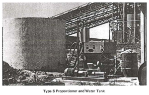 A dust problem was created and so Costains decided that dust control, using the Chem-Jet method, was necessary for this plant. To achieve the acceptable level of dust control, a Chem-Jet solution of up to 1% by weight is applied to every ton of material handled. The solution is automatically blended in a type ‘S’ proportioner and is then pumped under pressure to the 13 application points throughout the plant.
 The treatment is controlled from a central panel and automatic controls are located throughout the plant to ensure that the solution is not wasted, but applied only when coal is passing the selected application points.
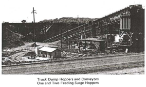
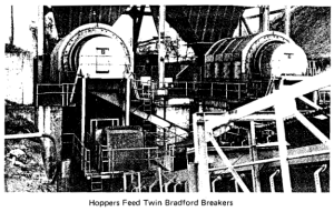 Coal is discharged from bottom dump 110 ton capacity trucks into 2 hoppers, and from there is fed by twin vibratory feeders to two 12′ diameter Bradford Breakers. A total of 28 sprays are located at the vibratory feeders and discharge from the breakers which prevents dust being liberated to atmosphere and commences pre-treatment of the coal.

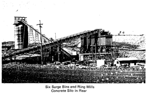 The third application takes place at transfer stations on conveyors 1 and 2. From the initial crushing, the – 8½” coal is transported to 6 surge bins and from these, the product is fed to 6 ring mills which produce – 1¼” coal. Sprays are located at each of the ring mills and a further application point is provided on conveyor No. 4. From this point the coal is conveyed a distance of 600 ft. to a concrete 6000 ton silo, before further shipment.
CHEM-JET CONTROLS DUST IN W.A. IRON ORE PLANT
 Handling iron ore always produces dust, especially in the hot dry climate of Western Australia. In an effort to reduce air pollution, Engineers and Management of the Dampier Mining Company Limited’s Koolyanobbing Crushing plant decided to install a Chem -Jet Wet Spray Dust Control System.
 The Koolyanobbing Crushing plant produces some 900 tons per hour of very dry and friable ore. Dump trucks of 50 short ton capacity discharge ore into the receiving hopper, it is then fed to the primary jaw crusher. The minus 9″ material is conveyed direct to twin secondary gyratory crushers. The product is then conveyed to a vibratory screen, which separates the minus 1¼” material with the oversize going to the tertiary gyratory crusher set to produce 1¼” ore. This combined material is then conveyed to the storage bunkers by inclined conveyors and travelling tripper conveyor.
The Chem-Jet Dust Control System prevents dust becoming air borne, by wetting the ore at all crushing and conveying points in the initial handling operation where dust is being liberated to the atmosphere. To produce the wetting action, a specially formulated surface active agent, known as Compound M.S.T . is  utilised. This highly concentrated chemical solution is mixed with water in small amounts, and sprayed in dust producing areas. The Compound M.S.T. is non-toxic, non-corrosive, odourless and fully biodegradable.
The heart of the Chem-Jet System is the proportioning unit, which automatically meters and mixes the M.S.T. Compound at a ratio of 4000 parts water to one part Compound M.S.T. The solution is then pumped into a specially engineered piping system for dispersal to the strategically located spray headers.
 Dust control begins at the truck dump hopper and treatment is given at 15 points which are automatically controlled by Chem-Jet Flow Controllers and Actuators. The Chem-Jet system has the capacity to add a maximum of 3 gallons per ton of moisture throughout the handling and crushing plant. In addition to effective dust control at the various application points, the carry over effect gained by the treatment allows screening, discharges to storage bunkers and eventual train loading to take place with out generating dust.
![]() The benefits obtained from this system by keeping the atmosphere clean are intangible. In addition to reducing material losses and improving employee morale, clean up time is cut to a minimum and equipment maintenance has been reduced.
The benefits obtained from this system by keeping the atmosphere clean are intangible. In addition to reducing material losses and improving employee morale, clean up time is cut to a minimum and equipment maintenance has been reduced.
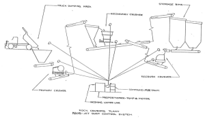
ROCK CRUSHING PLANT
Material flow starts at the truck dump, where the two headers (above and below hopper) are manually controlled by push-button switches. The crushed stone discharged from the primary crusher is treated before it passes to a sorting hopper, which diverts material of proper screen size to the storage bins. Out sized material is fed into the secondary crusher. Note that the material is treated both before d after crushing. This action is necessary to control the excessively dusty conditions created by the inevitable breaking up of the material in transit.
From the secondary crusher, the stone, now the same size as the screened material, is conveyed to the storage bins. In the example shown here, there is yet another material breakdown (there may be several more in a plant). The stone, then, is fed from the storage bins to the recrush crusher, where it receives another spray treatment. Crushing completed, the now properly sized and dustless material is returned to the bins for storage or sent out to the loading area.
Control of the spray jet headers at the discharge of the primary crusher and at the input and discharge of the secondary and recrush crushers is automatic.
COAL HANDLING, POWER PLANT METHOD NO.I, ROTARY CAR DUMPER
All sprays are off until the rotating platform has turned 18 degrees, when automatic control turn on the overhead spray to suppress the initial dust. At 37 degrees off vertical, the headers at the hopper mouth are set in operation. These three headers remain on until the dumping is complete. When outdoor temperature is below freezing, the header at the feeder is used alone for initial treatment. This header is actuated by a separate automatic control and may be operated independently of the others. After initial treatment, the dust-free coal is sent on to the breaker building without further spray application.
METHOD NO. 2, CAR SHAKEOUT
Here the headers are controlled manually by the shakeout operator, who starts the spray jets when the clamps have lowered over the car. The flow of material from the shakeout hopper is the same as from the dumper.
METHOD NO.3, BARGE UNLOADING.
With this method, the headers are controlled by the action of a limit switch placed along the trolley rails travelled by the bucket scoop. The headers operate only when coal is being unloaded into the hopper. In this application the dust itself is not treated. Instead, the area where the clam-shell is unloaded is curtained off by the Chem-Jet sprays.
METHOD NO. 4, CONTINUOUS HOPPER DUMPER.
Some unit trains provide for continuous dumping of coal while the trains move over a long hopper area under the track. The Chem-Jet System is similar to the car shakeout system. It extends for the full length of the dump area and is actuated by the presence of the loaded cars and the coal on the conveyor belts.
THE CRUSHER
From the initial treatment point the coal passes along a conveyor to a pair of chutes having a common mouth. if the coal is Lo be sent to storage (reclaim), it passes without treatment down the left-hand chute and out to the stockpile. If it is to be crushed and conveyed to the furnaces, it flows down the right hand leg and into the crusher. Since the coal is crushed here and new dust-producing surfaces created, the coal is given a secondary. pray application as it enters and leaves the crusher. DOO-10-005 During times when the crusher is running empty the sprays at the top of the crusher are automatically turned on for short intermittent periods to prevent dusting from the crusher.
THE RECALIM HOPPER
Coal drawn from open-air stockpiles usually has been in storage for days or even weeks. To ensure dust-free transfer to the crusher, the coal is treated at the reclaim hopper. Header control is accomplished by either an under-belt or over-belt automatic spray jet control.
MECAL-JET – MDS COMPOUND
MDS Compound is a non-ionic, fully bio-degradable, non-toxic, non-flammable and most effective dust suppressant.
MDS Compound is a Linear Alcohol Ethoxylate Chemical.
Effect of MDS on Product.
The small amount of moisture (MDS plus water) required to suppress dust is not harmful to most materials
- To suppress coal dust, for example, which is quite oily and moisture-resistant, requires the addition of only one-half of one percent (0.5%) or 5 litres of moisture per tonne of coal. This figure is the total amount of moisture added to the material, regardless of the number of spray application points.
This is based on a mixed solution of 1 part Compound MDS to 4000 parts water.
If water alone is used, much greater quantities of moisture must be added to do even a partially effective job. With just about any material, less than 1% total addition of mixed solution (moisture) is usually the maximum required.
- Compound MDS has no effect on a material’s burning qualities. The Compound vaporizes at 110° C, leaving no trace.
- Compound MDS mixed solution has no corrosive effect on machinery, belts, etc: this has been demonstrated on many Mecal-Jet installations over many years.
- For stockpiles or after shipment, the effects of Compound MOS can be ‘re-energised’ simply by respraying the product with water only.
(DOO-13-008/0002)
How does Compound MDS work?
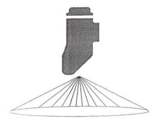
1. The basic principle: Compound MDS reduces the surface tension of water from about 75 dynes/cm to less than 25 dynes/cm. This reduction in surface tension improves water’s surface-active qualities, producing a solution with excellent wetting, spreading and penetrating powers. a) Where dust is of larger sizes (several microns or more) a droplet of water appear something like this:
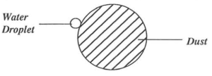
Note that there is very little contact between water and particle; consequently, there is very little effective wetting action. With a 1:1000 solution of MDS and water, the droplet has greater wetting and spreading power because of reduced surface tension. The particle is surrounded by water.

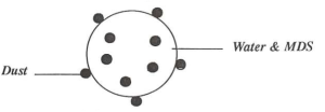
b) Dust of sub-micron size is smaller than droplet size. Interfacial tension (surface tensions of the material at point of contact) of dust and untreated water is such that dust does not enter the droplet; it forms a film.
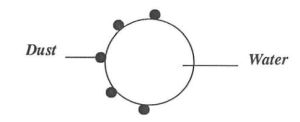
But with the same MDS and water solution as above, sub-micron dust is readily taken into the droplet.
c) Water wetted with MDS is, because of lower surface tension, more readily formed into smaller droplets, putting more droplets per unit volume into the air where they can make contact with dust particles. Larger droplets, it is obvious, would necessitate using more water to do the same job.
2. Compound MDS is not “just another wetting agent”. It has been specially formulated to provide the best combination of properties for most types of dust.
MECAL-JET USERS LIST
| AUSTRALIA | LOCATION | STATE | INDUSTRY | PRODUCT |
| Adelaide Brighton Cement | Kline Point | SA | Cement | Limestone |
| A.P.M. | Maryvale | VIC | Paper Mill | |
| Agnew Mining Co. | Leinster | WA | Mine | Iron Ore |
| Boyne Smelters Ltd | Boyne Island | QLD | Aluminium | |
| BHP | Stockton Bore | NSW | Mine | Coal |
| BHP Iron Ore | WA | Mine | Iron Ore | |
| Bell Basic Industries | Maddington | WA | Quarry | |
| C.S. Energy | Biloela | QLD | Power Station | Coal |
| Comalco Ltd | Weipa | QLD | Aluminium | Bauxite |
| Dalrymple Bay Coal Terminal | MacKay | QLD | Terminal | Coal |
| David Mitchell Estate | VIC | Quarry | Limestone | |
| Drayton Coal | Muswellbrook | NSW | Mine | Coal |
| Energy Resources Australia | Jabiru | NT | Mine | Uranium |
| George Fisher Project (MIM) | Mt. Isa | QLD | Mine | |
| Hymix Quarries | Gosford | NSW | Mine | Stone |
| J & A Brown | Catherine Hill Bay Hwiter Valley No. 1 | NSW | Mine | Coal |
| Mackay Sugar | Mackay | QLD | Sugar | Coal |
| Maritin1e Services | Balmain | NSW | Loader | Coal |
| Mt Gunson Mine | Woomera | SA | Mine | |
| Mt Leyshon Gold Mine | Charters Towers | QLD | Mine | Gold |
| Mt Newman Mining Co. | Tom Price | WA | Mine | Iron Ore |
| Newcom Collieries | Cooranbong Myuna | NSW | Mine | Coal |
| Pacific Power | Eraring | NSW | Power Station Coal |
| Liddell | |||
| Pivot | Geelong | VIC | Fertilizer |
| Port Waratah Coal Services | Newcastle | NSW | Loader Coal |
| Poseidon Gold | Tennant Creek | NT | Mine Gold |
| QEC | Callide ‘B’ | QLD | Power Station Coal |
| Gladstone | |||
| Stanwell | |||
| QEGB | Tarong | QLD | Power Station Coal |
| Queensland Alumina | Gladstone | QLD | Aluminium Alumina |
| Queensland Fertilizer (ABB) | Townsville | QLD | Fertilizer |
| Robe River Iron Associates | WA | Mine Iron Ore | |
| SEC of VIC | Loy Yang | VIC | Power Station Coal |
| Three Springs Talc Pty Ltd | Three Springs | WA | Mine Talc |
| Ulan Coal. | Ulan | NSW | Mine Coal |
| Western Power | Muja | WA | Power Station Coal |
| Westfarrners Coal | Muja | WA | Mine Coal |
| Whim Creek Consolidated | Meekatharra | WA | Mine Coal |
| INDIA | LOCATION | INDUSTRY | PRODUCT |
| Indian Aluminium Co Ltd | Mine
|
Haul Road Bauxite OverburdenBauxite Bauxite | |
| Mahanadi Coalfields Ltd IB-Valley Area, Chingriguda Belpahar | ORISSA | Mine 5.Haul Road 2. Crusher House 3. Stockpiles at Rly Siding Platform N: 1 & II | Coal |
| Pipawah (White Equipment) | |||
| Radiant Industries Ltd Birlah Copper Project | BHARUCH, GUJARAT | Mine
|
Lignite |
| Rashtriya Ispat Nigam Ltd Visakhapatnam Steel Plant Jagyapeta | ANDHRA, PRADESH | Mine Wagon Loading Hopper | Limestone |
| South Eastern Coalfields Ltd Kusmunda Area | MADHYA, PRADESH | Mine Stockpiles at Rly Siding Platform No: 1 & II | Coal |
| Steel Authority of India Ltd Bhilai Steel Plant | MADHYA, PRADESH | Wagon Tippler Track Hopper Central Storage Yard | Dolomite LimestoneLimestoneIrone Ore, Dolomite Limestone |
| MEXICO | |||
| Rio Escondido Power Station | Power Station | Coal | |
| Sicartsa | Mine | Iron Ore | |
| NEW ZEALAND | |||
| Electric Corporation | HUNTLEY | Power Station | Coal |
| Hauraki District Council | PAEROA | Mine | Limestone |
| PHILIPPINES | |||
| Solid Cement Corp. | Cement | Limestone | |
| TAIWAN | |||
| Taiwan Power Corporation | TAICHUNG | Power Station | Coal |
DUST SUPPRESSION QUESTIONNAIRE
We require you to fill up a questionnaire so we would know exactly what you need.
Click here to redirect you to the questionnaire:
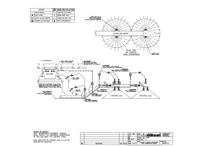
TYPICAL STOCKPILE SYSTEM